Transformer Rectifiers
In impressed current cathodic protection systems, are used transformer rectifiers to impressed electrical current into protected structures. Performance principles of transformer rectifiers are rectifying the input AC, impress and stabilization of current into the protected structure.
Cathodic protection transformer rectifiers suitable for use in a variety of environments such as humid, dusty, saltmarsh, indoors, etc. are permanently manufactured under full load with the following conditions in mind:
- Maximum temperature with shade: 50 °C
- Maximum temperature of metal surfaces directly exposed to sunlight: 80 °C
- Maximum relative humidity: 95%
- Isocronic level: 60 (60 days lightning per year)
- Approximate dust concentration: 70 to 1400 mg/m3
Types of transformer rectifiers in terms of cooling systems
- Air cooling (AN)
This type of transformer rectifiers are typically manufactured in the range of 10 to 50 volts and 5 to 30 amps, but on demand, the design and production of cool air transformer rectifiers are also possible at higher power.
- Oil cooling (ON)
In order to increase the reliability of the device in harsh conditions, transformer rectifiers are manufactured with oil cooling. In this type of transformer rectifiers, the rectifier bridge and filters are immersed in the oil and the oil tank is equipped with surface display, oil temperature and Dehumidifiers.
Types of transformer rectifiers in terms of control methodes
- Autotransformer control (regavolt) transformer rectifiers
In this type of transformer rectifiers, which are produced with single phase and three phase inputs, a variable autotransformer (VARIAC) is installed in the primary transformer circuit of the device. By this autotransformer, the primary voltage of the main transformer was adjustable from zero to maximum, therefore, the secondary voltage of the transformer also fluctuates between zero and the maximum nominal range, consequently, if the diode rectifier bridge is used, the rectified output voltage will likewise be adjustable.
The advantage of this type of transformer rectifiers is the continuous adjustment of the output voltage from zero to its maximum rated. Autotransformer transformer rectifiers are a constant voltage type that will supply the current required by voltage regulation. The major disadvantage of these transformer rectifiers is that by changing the electrical resistance equivalent of the cathodic protection system for any reason (such as rainfall, soil dryness, etc.) due to the voltage stabilization in the regulator range, the current fluctuation is altered, thus requiring the transformer rectifier to be reset.
- Electronic control transformer rectifiers
This type of rectifier transformer uses a thyristor rectifier bridge and typically, the rectifier is either a full-wave, semi-control or all-controller type, which is mounted on a secondary transformer and will change the output of the thyristors by means of an electronic control circuit. In thyristor rectifiers, depending on the requirements and operating conditions, the control can be considered as current source or voltage source.
- Constant voltage
In the constant voltage transformer rectifiers, the electronic control unit receives feedback from the output voltage and, by changing the input voltage and output current, stabilizes the output voltage to the previously set value. The weakness of constant voltage transformer rectifiers is similar to that of autotransformer transformer rectifiers. In this way, the reduction of the impressed current (due to the increase in resistivity of the earth) will cause the problem of under cathodic protection and if the increase of the impressed current (due to the decrease of the equivalent resistance of the system under protection) will cause damage to the coating of cathodic protected structure.
- Constant voltage
In order to solve the problem of visibility and adjustment of the constant voltage transformer rectifiers, the constant current and electronic control (AMP-O-MATIC) has been manufactured and marketed. In constant current transformer rectifiers, the output current remains unchanged by changing the equivalent resistance of the system under protection, which will cause the output voltage of the rectifier to change. If, for some reason, the equivalent resistance of the system under protection is increased to stabilize the impressed current, the output voltage proportional to the equivalent circuit resistance is increased. The output current is stabilized by the electronic control unit by varying the fire angle of the thyristors. The electronic control unit detects any change in the set current by sampling the device output current (by means of a sampling shunt) and stabilizes the output current by adjusting the fire angle of the thyristor. If the equivalent resistance of the system under protection is increased due to changing environmental conditions (eg season change), the output voltage is increased to 10% above the rated voltage of the device to stabilize the transformer rectifier current and prevent the adjusted impressed current change.
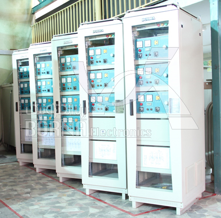
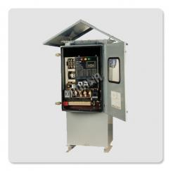
Multi-channel electronic control transformer rectifier with air cooling manufactured by Borna Electronics Co.
- Electronic/ autotransformer control transformer rectifiers (automatic/ manual)
This type of rectifier is recommended to increase the reliability of the electronic control transformer rectifiers and to ensure the output of the device in case of trouble in the electronic control unit. Since cathodic protection transformer rectifiers are typically installed in poor weather conditions and in remote areas and the defects in their electronic control system cause a timeout for the transformer rectifiers repair at the time of their failure, as a result, the structure is not cathodic protected and ultimately irreparable. In these conditions, the use of electronic/ autotransformer control transformer rectifiers is economical. In this way, if there is a problem in the output control unit, the output of the unit is not interrupted and the rectifier transformer will continue to operate with the autotransformer.
In this type of transformer rectifier, a variak device is installed in the primary transformer and the rectifier bridge is thyristor type, At the same time, an circuit is mounted on the rectifier section and when the rectifier transformer is set to regavolt state, the thyristors act as a diode and the output of the device changes as the autotransformer changes. It is worth noting that the device’s autotransformer is also in electronic control mode and output regulation can be adjusted simultaneously by the autotransformer and the electronic control unit.
- Smart transformer rectifiers
Considering that the development of microprocessor technology and its widespread application in various industries, especially control and protection, has been remarkable and significant and cathodic protection experts have always been looking for new methods and tools to improve cathodic protection systems, It also utilizes microprocessor scheduling and storage, as well as receiving reports from various microprocessors, while significantly increasing protection accuracy, extending life time of protected equipment, saving on-site cathodic field inspections, quick access to data and figures have provided.
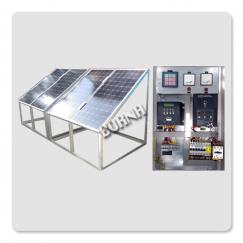
Smart cathode protection systems are ideal for installation in refineries, power plants, petrochemicals industries, intercity pipelines and etc. In this system, the potential of different parts of the system to the electrolyte (soil, water, etc.) is permanently (by permanent half cell) transferred to the transformer rectifier and the device, by means of an smart controller, regulates the output current, and puts the voltage at all test points within the cathodic protection criterion range. The main parts of these systems are:
- Transformer rectifier with microprocessor or microcontroller control
- Permanent half cell (permanent reference electrode)
Types of smart transformer rectifiers are as follows:
- Single reference control smart transformer rectifier
In single reference smart cathode protection systems, a permanent reference electrode is used to regulate the impressed current. Thus, by continuously measuring the potential of the structure under cathodic protection to electrolyte in contact with the structure, the output current of the transformer rectifier is regulated. The basis of the smart transformer rectifier control unit is to continuously control the reference potential and to change the pulse width and fire angle of the thyristors resulting in a change in output current. The process of this operation is to stabilize the reference potential within the cathodic protection criterion range.
- Multi reference control smart transformer rectifier
In single reference smart cathode protection systems, multi permanent reference electrode are used to regulate the impressed current.
The microprocessor unit of this transformer rectifiers consists of four parts:
- Receiving Unit for Input Samples (Permanent Reference Electrodes Potential)
- Input Processing Unit
- Display output unit
- Analog output unit
The input unit is capable of receiving and processing samples. The processing unit first receives all the samples from the input, then increases or decreases the analog output sample according to the potential of the half cells. This will set the samples at best.
Output remains constant while Half cell potential falls within the protection criterion range. During this process, the processing unit transmits the required information to the user through the display. If the potential of the samples is changed during cathode protection system operation, the processing unit immediately adapts the cathode protection system to the new sample conditions immediately by changing the output of the analog unit.
One of the features of the smart transformer rectifiers is the serial connection capability according to RS485 standard. This connection has enabled the creation of a network with BUS topology. According to this topology, all rectifier transformer devices are connected via a two-wire connection, and eventually connected to a server device (this server can exchange information and control with a computer).
Each transformer rectifiers has its own address inside the master server. The start of any communication will always be from the server, as the server first sends a signal containing the address of the unit to be communicated to the BUS. Therefore, the address is received by all units and the unit with the same address as the server is ready for further information and the next signal contains the command to receive and send information, then allow other commands to be sent.
With the above mentioned process it is possible to obtain various reports on the status of cathodic protection system and the potential of references. It is also possible to command any transformer rectifiers and thereby adjust the reference potential in the protection range.
Data exchange via landline (if possible) and mobile SIM card is also possible. In this regard, an interface is connected to the controller unit and transmitted via telephone call for relevant information and commands.
Smart transformer rectifiers have Local and Remote modes, in Remote mode the cathodic protection system is controlled by the server and in Local mode the adjustment is required at the stations and by the operator.
Borna Electronics Co. declares its readiness to design and manufacture all types of transformer rectifiers based on the requests of respected clients or project needs.