SDR

Protection against network undervoltage
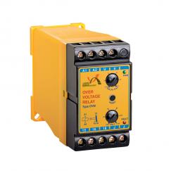
Protection against network overvoliage
30 A output current
5 KW output power
Having surge-absorbing timer
Having 7Segment display
U=220: Network voltage
T=240: ON delay
Signals:
RED Fault: ON Voltage under or over the allowed limit (on)
Delay: BLINK ON delay (blinking)
GREEN OUT: Guiput energization display
Principles of Operation:
Device starts working by network energization.
When network energizes. first. network voltage then ON delay time are shown on ciis- play.
Delay time (240 seconds) starts counting down and simultaneously. red signal blinks Till time ends.
Attention: tf voltage is under or over the allowed limit. timing does not start.
At the end of time. network voltage is shown on display: output energized and OUT signal gets ON.
lf volfage is under or over the allowed limit. output is de-enengized. green signal gets OFF and red signal (ON) gets ON.
lf network voltage gets back to normal. the above procedure repeats.
Installation and Start-Up:
Terminals MQ and PH have to be connect to network null and phase respectively. MQ and OUT terminals connect to air-conditioning compressor motor or single phase consumer.
Technical Specifications:
Network Voliage: 170 to 250 VAC
Network Frequency: 50 +5 Hz
Internal Loss: About 3 W
Undervoltage Fault: 175 to 180 VAC
Overvoltage Fault: 240 to 245 VAC
ON Delay: 240 seconds
Outout Current: 30 4
Outout Power: 5 KW