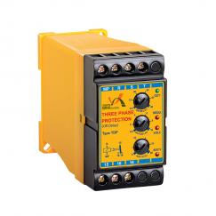
Recognition of asymmetry in voltage of three phases
Recognition of network undervoltage
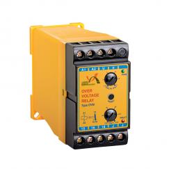
Recognition of network overvoltage
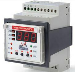
Having display signals of input supply, normal status (output energization), phase sequence, asymmetry in voltage of three phases, uncdervoliage and overvoltage
Instant disconnection at the time of fault occurrence
Connection Time selection capability, after error correction
Signals that display various errors and normal status
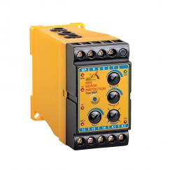
Protection of electro motors against network faults
– Phase disconnection
– Phase disclacement
– Voltage decrease more than the allowed limit.
– 3phoase voliage asymmetry more than allowed limits
– The consecutive power connection and disconnection shock
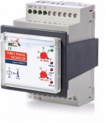
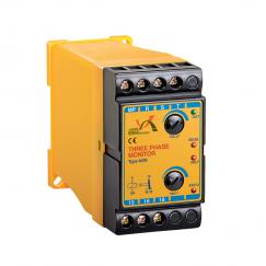
Principles of Operation
Affer connecting Null to MP terminal and phases to the T.3.R terminals. the device begins to operate. After each enor comection. the device begins timing. At the end of adjusted time (DELAY). OUT signal geis ON and device intemal relay gets connected (intemal contact of terminal 15 to 18 is made).
Attention: If the status of the 3 phases is not normal. the timing does not begin.
Incase cfaneror(suchosvoltage decrease. phase disconnection andorphase displacement) in 34ohase network. the foult signal gets on. and the intemal relay also gets disconnected simultaneously by the tum off of the output sgnal (intemal contact of terminal 15 to 16 is made.
Attention: in case of the existence of an emor in S-phase network at the beginning of the operation. the related signal wil remain on and the intemal relay will not get connected.