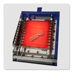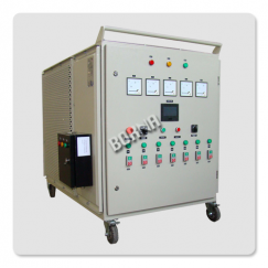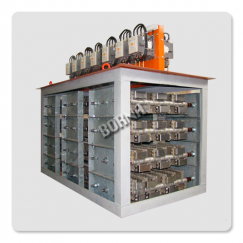
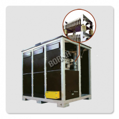
Motor Starting & Control Resistor
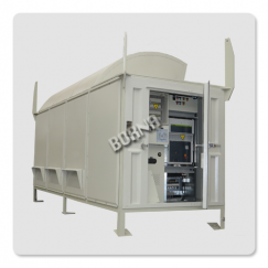
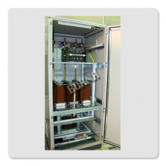
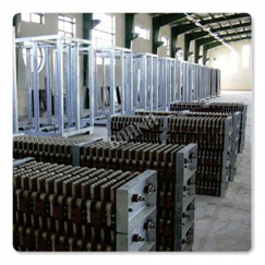
Industrial Power Resistor
Our Resistance Units are regularly Supplied for the Following Industries and application
Industries
- Generation
- Oil, Gas and Petrochemical
- Distribution Substation
- Gas Compressor Station
- Rolling Mills
- Electric Traction
- Testing Station
Applications
- Neutral Grounding Resistors (NGR or NER)
- Dynamic Braking Resistors (DBR› S)
- Motor Starting and Speed Control Resistors
- Testing
- Batteries
- Power Supplies
- Stand by Power Systems
- Dummy Load
- Load Banks
- Industrial Heaters
- High Power Variable Resistors
- Capacitor Charge/discharge Resistors
- Cranes and Other Load equipments
- Bow thrusters
Motor Control Resistors
Starting resistors are switchgears that take electrical machines from zero to operating conditions.
Motor control is one of the most common applications of power resistors. Resistors are used to control the torque and speed characteristics of AC and DC motors, and to limit inrush currents.
They can be divided into:
- Starting resistors for three phase motors with squirrel cage rotor
- Resistors for Torque-speed and start up current of three phase motors with slip ring
- Starting resistors for DC motors
- Wye – Delta starting resistors
AC Squirrel Cage Motor
In squirrel cage motors, the conductors in the rotor slots are shorted at the ends. Therefore, the resistance of the conductors is fixed and can not be changed. However, resistors can be connected in line with the motor to reduce the starting voltage. During the acceleration period at the moment a motor is started, it draws a high inrush current.
Resistor can be used to reduce the full line, starting voltage applied to the motor. Commonly known as a ballast resistor, the resistor acts as a voltage divider and reduces the inrush current, providing a soft start.
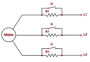
Typical resistor control schematic for an AC squirrel cage motor
Slip Ring Motor (Wound Rotor Induction Motor)
In wound rotor motors, the conductors in the rotor are connected to slip ring. The internal brushes make electrical contact with the slip rings and are connected to an external resistor circuit. By varying the external resistance the rotor current can be changed to control the starting torque and speed of the motor to meet the requirements of any installation.
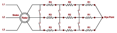
3 Step / 4Speed
Typical resistor control schematic for an AC wound rotor RT=Rotor voltage / (1.73 * rotor current * k) k is torque coefficient
DC Motor
In DC motors unlike AC motors, reactance can not play a role for current limiting. Hence the locked rotor current and starting current of DC motor is much more than same power rating AC Motor.
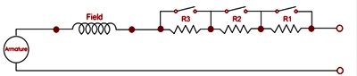
Typical resistor control schematic for a DC Series wound motor
Starting resistors shall be located in series with armature circuit and in a number of steps they have to be by passed with do contactor.
Why-Delta Type Starters (Closed Transition)
In the case of Y- closed transition type starter, a set of resistors are connected to the motor winding after wye contactor opens and before the delta contactor is closed. These resistors are used to balance the back EMF of the motor and the line voltage before closing the delta contactor.
Closed transition eliminates the surge current that occurs when transferring the motor from wye (Y) to delta ( ) connection, thus providing a smoother acceleration of the motor from reduced voltage to full voltage.
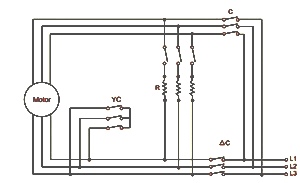
Y- ∆ Resistor starting schematic
For ordering the following data is required
- Motor Type
- Motor Power Rating
- Motor Application and Load Type
- Nominal Voltage and Nominal Current
- All of Nameplate Information