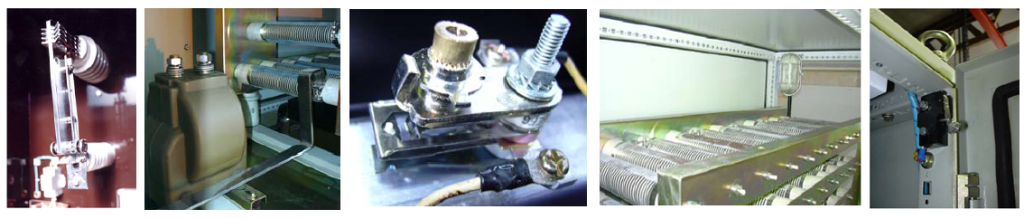
In the design of industrial power networks, various methods exist for electrical grounding. However, one of the most common methods, due to the appropriate advantages it creates in networks, is the grounding system using a resistor. This equipment is known as a Neutral Grounding Resistor (NGR).
Advantages of Using the NGR Neutral Grounding Resistor Device
There are three drawbacks in an ungrounded system.
1-Amplification of faults caused by switching overvoltages

2-Increase in the effect of two simultaneous single-phase faults to the level of a line-to-line fault

3-Increase in phase voltage and creation of insulation damage at the moment of a single-phase fault due to the floating neutral point

Installing an NGR device in the network, in addition to eliminating the above-mentioned defects, also results in achieving other advantages.
Grounding resistors are used in electrical grounding in AC networks with balanced loads and are installed between the neutral point of the generator or transformer and the ground. In this way, the network, in addition to benefiting from the advantages of a grounded system, will also perform very well in the event of a single-phase short circuit, and the fault current will be reduced to an acceptable level. Under such conditions, if a delay occurs in disconnecting the network, the fault current will not cause damage to network components because the fault current has been reduced to a tolerable level by the NGR.
According to IEEE142-1991 standard, the advantages of using a grounding resistor device are as follows:
- Reduction of damage caused by melting and burning at the short-circuit location
- Reduction of mechanical stress on equipment and devices through which the fault current passes
- Reduction of electric shock hazards to personnel caused by single-phase fault currents on the return path to the neutral point
- Reduction of electric arc and reduction of danger for personnel located near a single-phase fault
- Reduction of voltage rise caused by short circuit for other phases
- Reduction of transient overvoltages caused by short circuit
Types of Resistance Grounding
In general, there are two methods for grounding a system using resistance:
- Low resistance grounding – the explanations provided below fall within this category.
- High resistance grounding – what is referred to in the discussion of the NGC device is related to this method.
Therefore, to inquire about or order NGR devices, the main information including operating voltage, current, resistance value, and device operating time must be provided to this company.
Accessories, environmental conditions, and enclosure protection degree are among the items that, if stated by the purchaser, will increase the accuracy and quality of the response tailored to customer needs.
Selection of Grounding Resistance Values
The selection of NGR values is related to network calculations, in which the following items are considered:
- Maximum tripping time of network circuit breakers considering zoning, Earth Fault relay settings, and the presence of reclosing relays, which is generally considered to be about 10 seconds
- Single-line diagram of the network considering CT ranges
- Complete information on the weakest network component in terms of short-circuit current withstand capability
- Symmetrical three-phase short-circuit current
- Maximum allowable fault current of the network
By considering the above items, the four main parameters of the grounding resistor device—namely voltage level, current, resistance value, and operating time—must be determined.
Determining the voltage level is generally equivalent to calculating the maximum single-phase voltage.
In calculating the current, the first parameter considered is that during a single-phase short circuit, the resistive component of the single-phase fault current should not be less than the sum of the capacitive components of the three-phase current and should be approximately three times greater (most designers consider a threefold difference in calculations).
IR = U / R
IC = U / XC
XC = 1 / WC
∑IC = 3U / WC
C can be the capacitive value created between transformer windings and ground, transformer output cables to switchgear, switchgear outgoing feeders, etc., which varies in different networks. As an example, the total existing capacitive value in one of the projects carried out by this company at a 63/20 kV substation was 2.873 microfarads.
IR ≥ ∑IC ⇒ U / R ≥ 3U / WC
R ≤ 1 / 3WC∑
On the other hand, R = VPhase / ILimited, which is acceptable only if the above condition is satisfied. That the NGR current must be higher than the calculated value is obvious, but determining the upper limit of this current and ultimately selecting the final current of the NGR device depends on the current withstand capability of the weakest network component and the size of the low-voltage network.
With the voltage and current values available, dividing them will result in calculating the resistance value of the NGR device.
The operating time, as mentioned above, is determined based on the fault detection speed and the tripping of main breakers, considering reclosing relays, and is generally selected as 10 seconds.
Standard and Testing
Currently, the only existing standard in the field of grounding resistors is IEEE32-1972, titled:
IEEE Standard Requirements, Terminology & Test Procedure for Neutral Grounding Devices
This standard applies to all grounding devices, and Section 10 of this standard specifically addresses grounding resistors.
According to the mentioned standard, the tests performed on grounding resistors include:
- Resistance measurement – according to Section 10-1-4 of the standard
- Dielectric test – according to Section 10-3-2 of the standard
This company is capable of performing both of the above tests in its high-voltage laboratory.
Technical Specifications
- Environmental Conditions
Temperature: from -15°C to +60°C; temperatures outside this range must be declared by the customer at the time of inquiry.
Altitude: up to 1000 meters above sea level is considered in design; higher altitudes must be declared by the customer at the time of inquiry.
Humidity: up to 100%
- Types of Elements
- Wire Wound

Wire Wound resistor with ceramic core

Wire Wound resistor with porcelain core (H.V)
- Spring

Spring type resistor
- Edge Wound

Edge Wound type resistor
- Grid

Grid type resistor
- Ribbon Type

Ribbon Type resistor
- Casting Alloy

Casting Alloy resistor
3.Enclosure
1.Suitable for outdoor or indoor environments
2.Protection degree minimum IP23 up to maximum IP55
4.Input and Output Terminals
1.Input terminals: HV bushing type insulators installed inside a lockable box with IP54 protection degree. Installation of a suitable brass gland or aluminum gland plate at the bottom of the box is also considered in the terminal box construction.
2.Output terminals: LV bushing type insulators installed at the bottom of the device.
5.Accessories
These accessories will be installed on the device based on order:
- Monitoring relay, which allows detection of device continuity and occurrence of Earth Fault
- Disconnect switch (isolator) in manual and motorized types
- Current transformer and voltage transformer if required
- Thermostat in cases where a built-in thermostat heater is not used
- Microswitch